Repositories #
Super Power: Leto a Raspberry Pi UPS Solution #
Project Goals #

Develop a community-based, and hence user sourced, multifunction UPS solution for use with the Raspberry Pi main SBC platform (currently RPi3 and 4 models). The board is designed to provide remote power or UPS solutions. Provisions are included for both USB and auxiliary input power. Power is fed to the RPi GPIO header.
*** This document is currently in DRAFT *** *** Edits, corrections, and improvements are very welcome! *** *** The RPi Leto Team ***
Feature Descriptions #
The board can operate islanded by using a connected battery pack or the board can be used as a UPS solution leaving the board connected to a power source. Leto supports charge while operating, providing uninterrupted RPi operation.
The onboard controller includes communication features and expandability for future development. Included are a RTC and I2C communications to the host RPi platform. The inclusion of the RTC permits the Leto board to provide scheduled RPi operation. Physical connection to the RPi GPIO header accommodates a safe-shutdown hardware signal feature for use in either scheduled operation or low-power UPS safe-shutdown.
The included I2C communication permits higher level functionality and data exchange between the Leto uC and the RPi. This permits functionality such as charge state, voltage levels, and access to Leto hardware level registers. The uC permits additional communication provisions for secondary I2C and CANBUS for future feature integration.
The Leto board is designed to be firmware configurable from the RPi using the project development framework and debugging solution. This provides first-time users an out-of-the-box boot and flash configuration without the use of additional or separate hardware.
Because this is a community project, the board includes additional hardware features for expandability, testing, and alternate uC configurations. The team worked to balance features to include provisions for cost, platform flexibility, education, and to address a solution not available on the market.
Design #
The board is separated into seven functional areas. There is an accompanying project schematic for each area:
- Input Source
- Charger
- Battery
- Boost Converter
- Output Protection
- MCU
- Output Connections
Input Source #
The input source permits for connection to either a USB type-C connector or screw terminals. The team selected USB-C for its higher power capacity specification over the previous version of USB and that current versions of RPi 4 are configured with type-C. This permits the end user to use their existing power supply to power the Leto project.
Recognizing that many other options for power are available, the team provided screw terminals to permit the connection of alternate sources. One considered use case is a remotely managed and voltage regulated solar array.
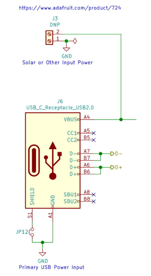
The Leto board is designed to charge and run on a 5V power source, but the onboard charging uC can accommodate input voltages on the screw terminals between 4.5 V and 14V. The data pins on the USB connector are connected to the charging uC to permit full use of its hardware features. The charging uC supports OTG USB functionality.
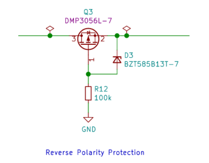
Input conditioning includes reverse polarity protection via MOFSET Q3.
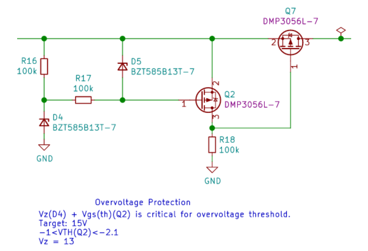
Overvoltage protection via the circuit using Q2 and Q7.
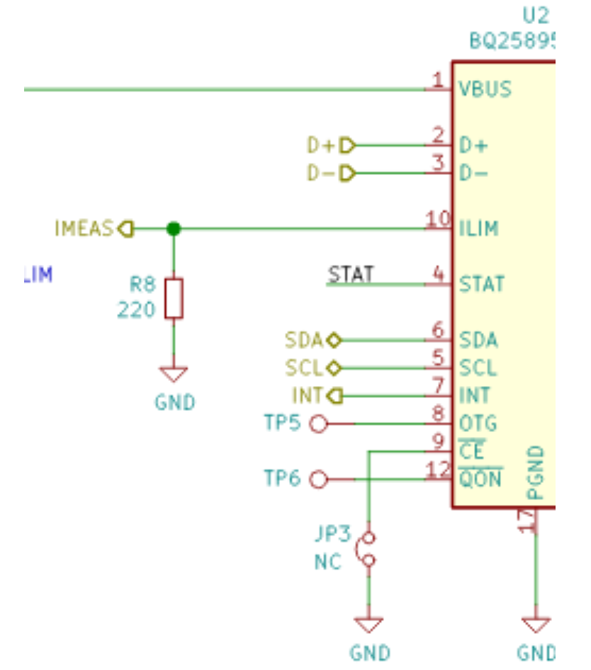
Charger #
The Leto project selected the TI BQ25895RTW battery charging uC for its feature set and ability to provide 3.0A to the connected load. While the RPi in base configuration does not regularly exceed 1.0A of current draw, the team wanted to ensure that the Leto project matched the 3.0A power source regularly provided with the RPi 4. This additional current overhead permits the use of attached peripherals such as an SSD, field sensors, overclocking, and active cooling.
The current overhead also permits the battery charge uC to operate well below its thermal limits during regular use.
The charger uC uses internal voltage conversion circuitry to control battery charge curves and its externally connected boost converter circuit to regulate the output voltage.

Additional selection criteria for the charge controller uC included a boost frequency that would not cause problems with the RPi and onboard ADC for battery state communication to the main uC and RPi.
The battery charge uC communicates with the Leto host uC over I2C.
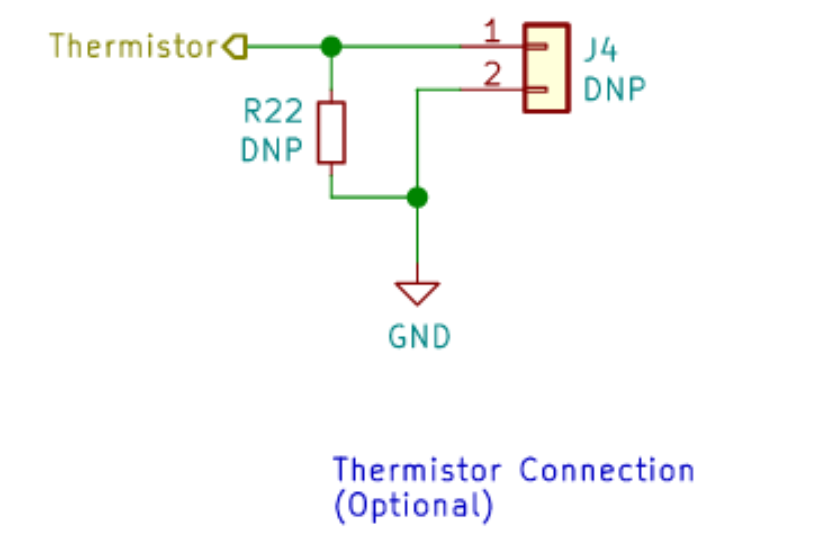
There is a provision for use of a remote battery thermistor for advanced battery charge management.
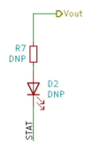
An onboard LED indicates the presence of voltage on the output of the charging uC.
Current limiting functionality is available on the charger but is not implemented in this version. IMEAS is provided for future feature addition or for the end user to add features.
Battery #
The project is designed for use with a 2800 mAh Li-Ion 18650 3S battery configuration. Nominal battery voltage design is 3.7V. The charging uC does not include functionality for cell balancing. This was not implemented due to the nature and variation of potential user connected sources.
The Leto project is not designed for use with multicell packs arranged in a series configuration with voltages over 3.7V.
Recognizing the possibility of user error, the battery circuit implemented polarity protection through Q1 and Q6.
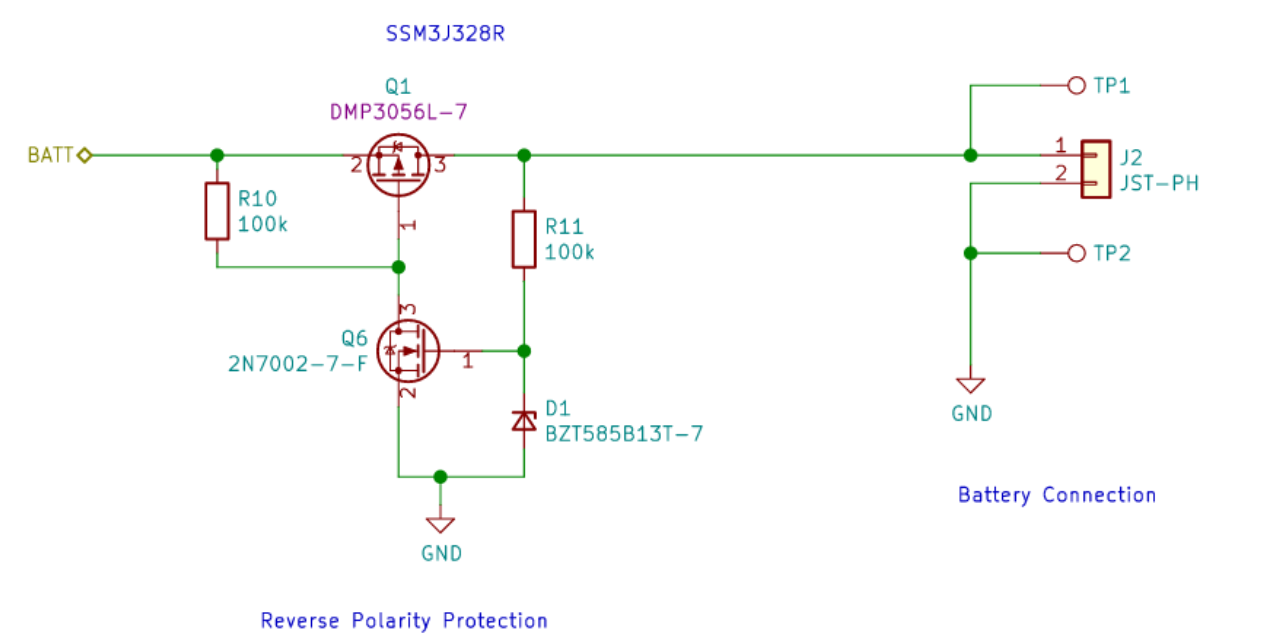
The board includes multiple test points for the end user to explore and measure board functions. TP1 and TP2 are provided to manually test the voltage across the battery connectors.
The optional battery thermistor can be connected at J4. The thermistor must be a negative temperature coefficient style. The recommended unit by TI is a 103AT-2.
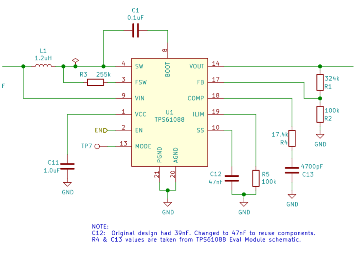
Boost Converter #
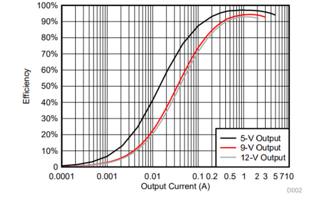
The boost converter steps the charger output voltage to the target Leto supply voltage. The TI TPS61088 package provides for a peak 10A capacity and internal thermal shutdown protection.
When operated in the target output range of 5V and between 0.5A and 3A, this boost converter achieves 95% efficiency. The configurable switching frequency permitted the team to design a boost converter that would not cause RPi interference.
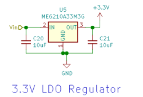
On board power for the Leto 3.3V control components is provided by U5:
Output Protection #
The leto project provides output protection using a current regulating circuit connected downstream of the boost converter. The NCP380 regulates output current in a short condition using internal MOFSET switching.
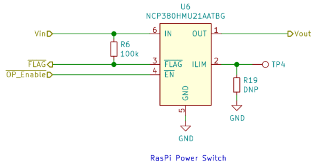
The OP_Enable signal permits the Leto uC to switch off power the connected RPi and the FLAG signal indicates a circuit protection state.
The team would like to see additional output signal quantification in future revisions to calculate total power consumption and provide estimated UPS or battery run times. This feature is not yet implemented due to const and limits on revision one complexity.
Output Connections #
The Leto RPi power management project is designed to be an under-slung solution. The end user is required to assemble provided pogo pins to make connections to the underside of the RPi GPIO header. The end user can alternately select to mount a standard GPIO shield connector.
An under-slung arrangement using the standard shield footprint was selected to permit the use of active RPi cooling or not interfere with other shields.
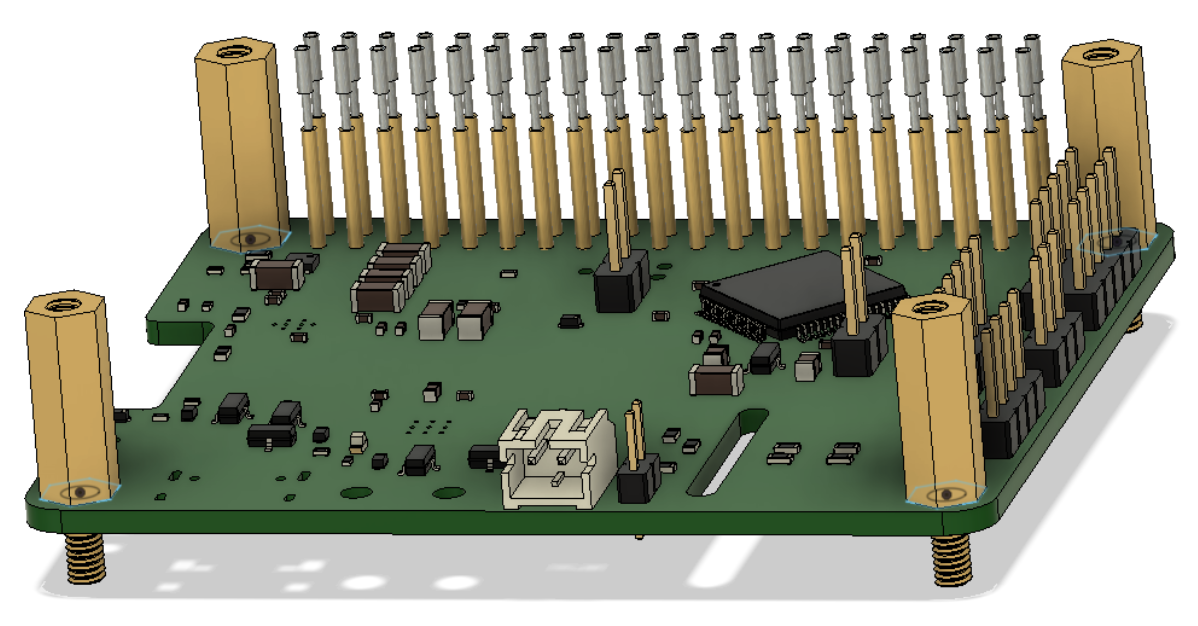
Note: in the render above all of the GPIO are populated. The end user only needs to solder the required GPIO pins identified in the schematic below:
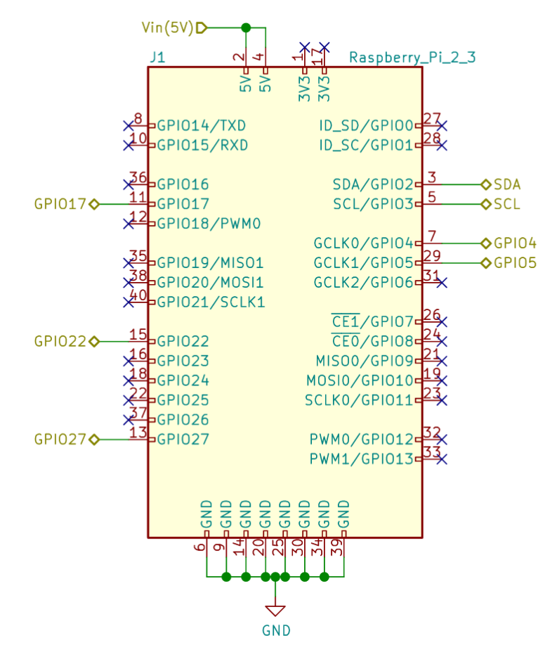
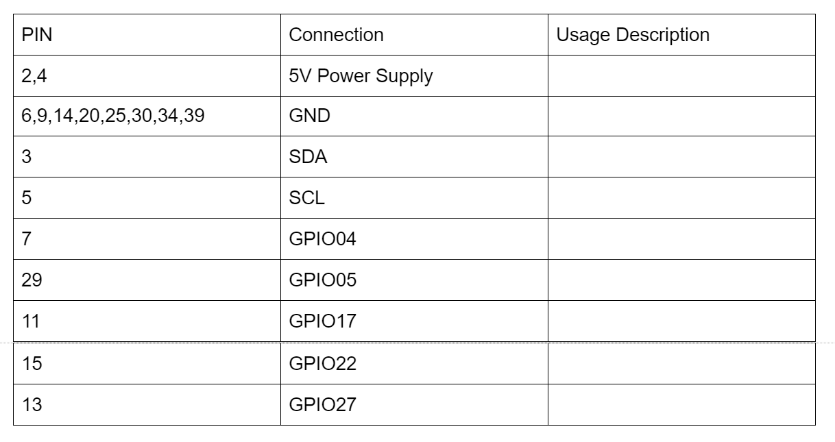
The Leto board pin connection functionality is as follows:
Previous Overview #
Block Diagram #
The Super Power RPi edition is a battery backup unit for the Raspberry Pi single board computer. It is meant to work with the Raspberry Pi 3 and 4.
Design #
The design is based on the bq25895 charger IC and the TPS61088 boost converter IC. It also integrates an STM32F412 microcontroller to provide timing and control independent of the Raspberry Pi.
The bq25895 provides some specific benefits for this project. It has a low series resistance in it’s FET, so the resistance between the battery and the boost converter is quite low. It also automatically negotiates higher power USB charging. Finally, it has significant internal monitoring, which eliminates the need for external components such as an ADC.
The STM32F412 was selected as it has quite a few internal peripherals to choose from. It also has a built in RTC, which allows for maintaining time even between power cycles.
In addition to the STM32, the footprint for an ATTiny85 was provided, but not populated, such that if anyone wants to use that series of MCU, they are able.
Physical Form Factor #
The Super Power RPi takes the shape of a Pi HAT PCB. It is designed to be used as either a traditional HAT, or in an underslung configuration.
The traditional HAT makes electrical connections using the 40-pin header and it is secured using the mounting holes at the 4 corners.
The underslung configuration also uses the mounting holes, but makes the electrical connections using pogo-pins. The pogo-pins connect to the 5V, GND, and I2C pins. The standoffs to be used are ____mm tall.
Use Cases #
Generally speaking, any situation that needs a Raspberry Pi to operate on batteries can be a potential use-case for this design.
More specifically, the following use cases were considered:
- Uninterruptable Power Supply (UPS). In cases where there is a potential power interruption, the Superpower provides backup power so the Raspberry Pi does not have an unexpected restart.
- Portable Pi. In cases where it is desirable to have a portable Pi or a Pi that will operate for extended periods of time using something other than “commercial power mains”, such as amateur radio Field Day competitions. This can be used to provide a computer that meets this criteria.
Potential future versions #
- Build a specific version that includes a solar MPPT IC.